Steel Connection Design
Steel connections are the backbone of steel structures, ensuring their integrity, stability, and longevity. Over the years, advancements in technology and design methodologies have transformed how engineers approach these crucial components. As we move into 2025, new materials, software innovations, and efficiency-driven methodologies are reshaping steel connection design.
Understanding Steel Connection Design
Steel connections link two or more structural elements, distributing loads and ensuring overall stability. Proper design involves considering load transfers, durability, and compliance with industry standards. The primary categories of steel connections include:
- Bolted Connections – These connections are preferred for ease of installation and maintenance. Bolts are characterised by high strength and resistance to shear and tension. The most common bolt classes are 8.8 and 10.9, while classes below these (such as 5.8) are often used for ancillary structures like railings, ladders or façade substructure elements. In the imperial system, classes A325 and A490 are the most frequent.
Bolts are usually installed at the construction site, which means that the dimensions of structural elements (beams, columns) can be significantly reduced (by separating the structure into several smaller units instead of large welded sections), which may play an important role in transport and site arrangement considerations.
Using bolts also allows for creating connections by way of slotted holes that facilitate the movement of the node in a particular direction, which is vital for structures such as bridges where huge thermal stress and deformations may occur due to their dimensions.
Bolted connections can be preloaded (slip-resistant), where the shear force is transferred via friction between two bolted contact surfaces, and non-preloaded (where slip is allowable), where the shear force is transferred through the bolt itself. Bolt preload is achieved by tightening and the requirements for the degrees and methods of tightening are laid out in execution standards such as EN 1090-2. Preloaded bolts are most commonly used for connections subjected to dynamic loading, such as connections in bridges and craneways, as these bolts are highly resistant to stress, or for girder extensions where any slip in the connection might lead to large deflections and redistribution of the forces not factored in at the initial structural design.
Apart from fatigue, the structures subjected to dynamic loading are also prone to self-loosening. This phenomenon occurs when the structure – as well as its bolts – are exposed to frequent vibrations (for example, structures serving as load-bearing elements and supports for rotating machinery). In such cases, apart from routine inspections, special mitigating measures are advisable that will prevent self-loosening, such as using double nuts or bolt assemblies with nuts and washers specifically designed to prevent self-loosening.
- Welded Connections – Contrary to bolted connections, welded connections are permanent, meaning they cannot be removed without destroying the joint itself. Welding is most commonly executed in workshops, in a controlled environment, and such welded assemblies are then transported to the construction site to be installed, usually using bolts. However, welding can also be done on site (at the construction site) although this method has disadvantages compared to welding in workshops, including additional corrosion protection of the weld and its surroundings and more difficulty in welded joint inspection, all of which renders this connection type more expensive. Welded connections have greater strength and offer a higher degree of stiffness compared to bolted connections.
From the aesthetic aspect, welds are certainly superior to bolted connections as members are smoother and continuous, with hardly visible connection points. Also, for structures where airtightness is of primary importance (tanks and pipelines, for instance), welded connections have proven to be the most efficient solution. However, welding requires much greater precision, longer preparation and execution, more expensive equipment and extensive expertise of the welder.
Since welding essentially means connecting the elements by melting together their connecting points, lines or surfaces, it is vital that welds are compliant to applicable standards such as EN 1090-2 or AWS D1.1. Welds must not contain bubbles of trapped air or contaminants, must not be uneven or of unequal thickness, as each of these defects may substantially compromise the resistance of the connection.
Meticulous attention needs to be paid to the process of cooling of the weld, as the shrinkage occurring after cooling can cause cracks to form, which in turn may develop into ruptures compromising the strength and anti-corrosion properties.
Since elements are connected by melting the metal at high temperatures, the microstructure of the metal is altered in the heat affected zone, which should be taken into account in the strength analysis. This effect is especially pronounced in welded connections in aluminium structures, and must routinely be included in the analysis of such structures.
There are various types of welds depending on the geometry of the connection and the most common ones in building constructions are fillet welds, where two elements are connected at an angle (usually between 60° and 120°), and butt welds connecting the members that are situated in a single plane.
Being structural discontinuity points, they represent locations with a potential for concentrations of strain, so for structures subjected to dynamic loading it is mandatory to check all types of welds for fatigue as well as to apply a stricter level of standard in execution comparing to structures subjected to predominantly static loading. - Hybrid Connections – A combination of bolted and welded techniques, hybrid connections leverage the advantages of both methods for optimized performance in complex structures. It is highly important to emphasize that only preloaded bolts may be used in hybrid connections.
Best Software Solutions for Steel Connection Design
Standards like EN 1993-1-8, AISC 360 (Chapter J) or AS 4100 (Chapter 9) regulate the field of steel connection design. They lay out provisions for determining the resistance of bolts and welds at nodes and provide data on allowable weld sizes, the minimum and maximum bolt spacings etc. In addition, there are other various documents providing guidelines for steel connection analysis and design, most notable being the documents published by the British Steel Construction Institute (SCI) P358 – Simple Joints to Eurocode 3 and P398 – Moment-Resisting Joints to Eurocode 3.
There is a number of commercial and free software tools and spreadsheets available that can be used to check code compliance of connections. Most of these tools, however, are limited to standard and prevalent connection types and offer limited options for analysing complex and nonstandard connections.
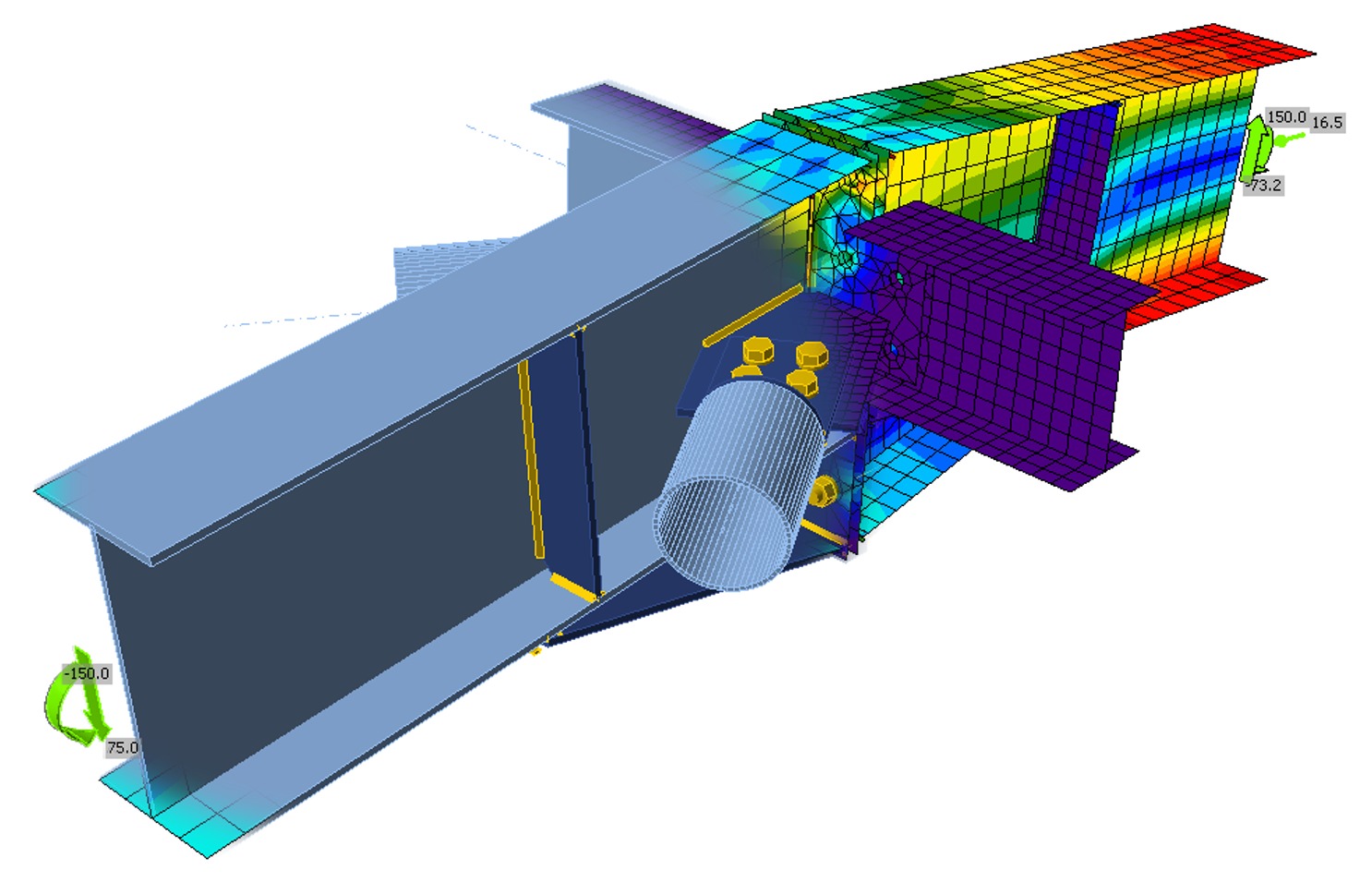
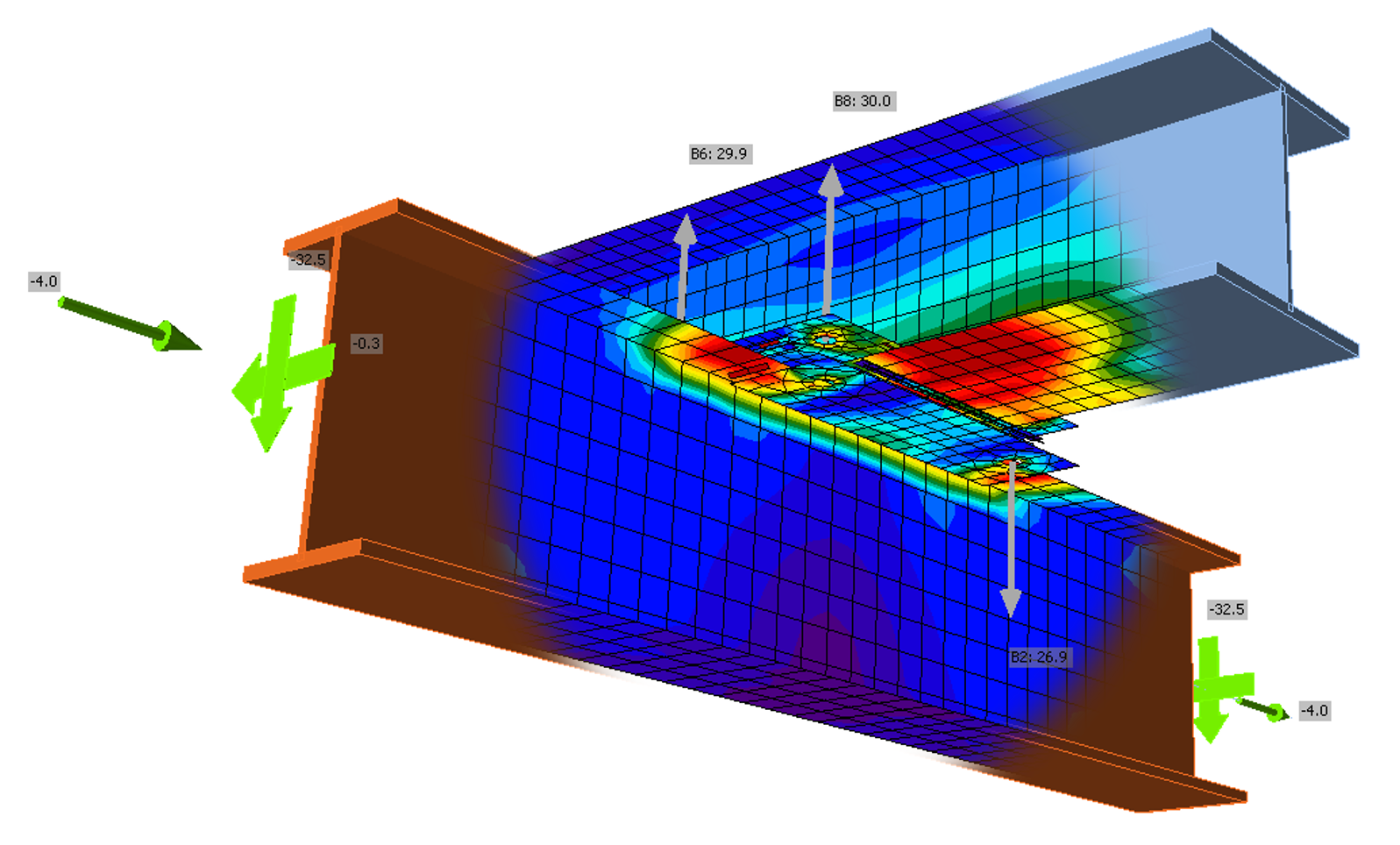
One of the potential solutions for designing complex connections (as well as the standard and simple ones) with precision is to apply FEA and to model the connections in a specialised software. Most prominent among such software tools is definitely IDEA StatiCa, the software that combines an advanced analysis of nodes with the Finite Element Analysis and further extraction of results and automatic inspection of elements according to the desired standard. This ensures unparalleled flexibility in analysis and design. Apart from the strength analysis of connection elements (base plates, bolts, welds), this software also offers the following:
- Stress and stiffness analysis
- Buckling and fatigue assessment
- Fire resistance check
- Seamless integration with global BIM tools like Tekla Structures and Autodesk Revit
The feature for geometry and load data import from other design platforms streamlines workflows, reducing design time and human error.
Emerging Trends in Steel Connection Design (2025 Edition)
1. AI-Powered Optimization
Artificial intelligence is revolutionising steel connection design by automating routine calculations, detecting potential weak points, and recommending optimal configurations. This reduces material waste while ensuring compliance with evolving industry standards. Further development of AI tools is expected to boost efficiency and streamline the entire connection design process. There are already solutions available that recommend connection types with predefined plate thicknesses, the number of bolts and their diameters and weld thicknesses based on the intensity of actions on the node and the location of the node (for instance, for beam-to-column or beam-to-beam joint configurations). It is up to the engineer, of course, to perform in-depth safety and code checks of the connection to ensure that all elements are safe and fully compliant, but such connection design process represents a highly efficient solution, especially for large and complex structures with numerous nodes.
2. 3D Printing in Steel Fabrication
Additive manufacturing is enabling the creation of customised steel joints with intricate geometries that were previously unattainable. This technology is particularly beneficial for high-stress or architecturally unique projects.
3. Sustainable Materials & Design
Sustainability is driving innovation, with engineers exploring high-strength recycled steel and alternative fastening methods that reduce embodied carbon. Energy-efficient fabrication techniques, such as laser welding, are gaining popularity for their precision and minimal environmental impact.
4. Enhanced Simulation & AR Integration
Augmented Reality (AR) tools are now integrated into steel connection design, allowing engineers to interact with and test their designs in immersive 3D environments before fabrication. This leads to better visualization and error detection.
Final Thoughts: What Lies Ahead?
Steel connection design is more sophisticated and efficient than ever, thanks to cutting-edge technology and a greater emphasis on sustainability. Engineers who stay up-to-date with the latest software tools, design methodologies, and best practices will be well-equipped to tackle the challenges of 2025 and beyond.
For further insights and expert guidance on steel connection design, feel free to reach out to our team at TIM GLOBAL ENGINEERING. We’re here to help you navigate the evolving landscape of structural engineering with confidence.