Wind Load: Key Factors in Designing – Part 1
Wind load is one of the key forces influencing the strength and stability of structures, be it a building, bridge, tower or any other structure out in the open, i.e. any other structure exposed to the climate and the weather. Of course, most structures satisfy this condition. Exceptions include, for example, industrial platforms which are located inside a building or a hall and are thus protected from the wind action. Wind generates actions perpendicular to the surface of the structure (and parallel, in cases involving wind friction), most frequently producing global horizontal and uplift forces, which can result in the loss of global stability (overturning, sliding or uplifting of the structure), increase in the internal forces of its elements and connections, or even damage to the elements or claddings if structural design is not adequate.
The wind action on the structure is dynamic in nature, but structural analysis treats it as a static action. Wind force intensity depends on the location of the structure (wind speed, air density, orography and roughness of the terrain) as well as on its own shape and geometry. To determine the load, engineers apply rules provided in various standards such as Eurocode 1 (EN 1991-1-4), ASCE7 or AS/NZS 1170.2. Understanding the effects the wind causes to and inside the structure helps in ensuring that the structure is safe and durable, especially in the conditions of ever-growing climate extremes. For this reason, this article will look into different structure types, their characteristics and how they are affected by the wind, as well as the aspects that require particular attention.
Buildings
Topping the list, of course, are buildings. Be it a residential or commercial facility or an industrial hall, the very form of this structural type dictates the nature of the wind load. In terms of wind load, this type of structure is defined as a roofed construction, enclosed by walls or façade on all sides, with a small percentage of openings in the building envelope (restrictions pertaining to the percentage of openings are defined in applicable standards). In most cases, the wind is not a governing horizontal action for concrete and composite structures in seismic zones, where the resulting seismic impacts are much larger than those from the wind due to a larger structural mass.
There are exceptions here too, such as high-rise buildings (skyscrapers), which require checking for the dynamic impacts of the wind to the structure, i.e. the possibility of resonance occurring. Steel buildings, especially halls, are much more susceptible to the wind actions (in terms of statics) than to the seismic actions, specifically due to their lower structural mass compared to concrete structures of the same size. The wind acts on the walls and the roof by pressure or suction. Peak velocity pressure is determined using the definitions provided in standards and is in the function of the structure’s height. The wind acts on the external area of the structure, but also on the internal area due to openings in the building envelope or permeability and porosity of the envelope itself. These actions are factored in through external and internal pressure coefficients (cpe and cpi in the Eurocode). The coefficient values provided pertain to walls and roofs and are in the function of geometry and dimensions of these structural units, i.e. shapes and dimensions of the structure’s base and the shape of the roof (flat, monopitch, duopitch etc.), and the slope and dimensions of the roof plane.
The Eurocode provides for the pressure coefficient values for vertical walls only for buildings with a square or rectangular base, while in practice there are many buildings with irregular-shape base. In this case we can make approximations and divide the base into designated parts, and then apply Eurocode rules or perhaps search for some other reference standard in which to find pressure coefficients for the desired case. For example, the withdrawn British standard BS 6399-2 (superseded by the Eurocode, but it does not include the provisions given hereunder) gives the instructions for determining pressure coefficient values and action zone dimensions for certain building types with re-entrant corners and recessed bays, as well as for buildings with different height segments.
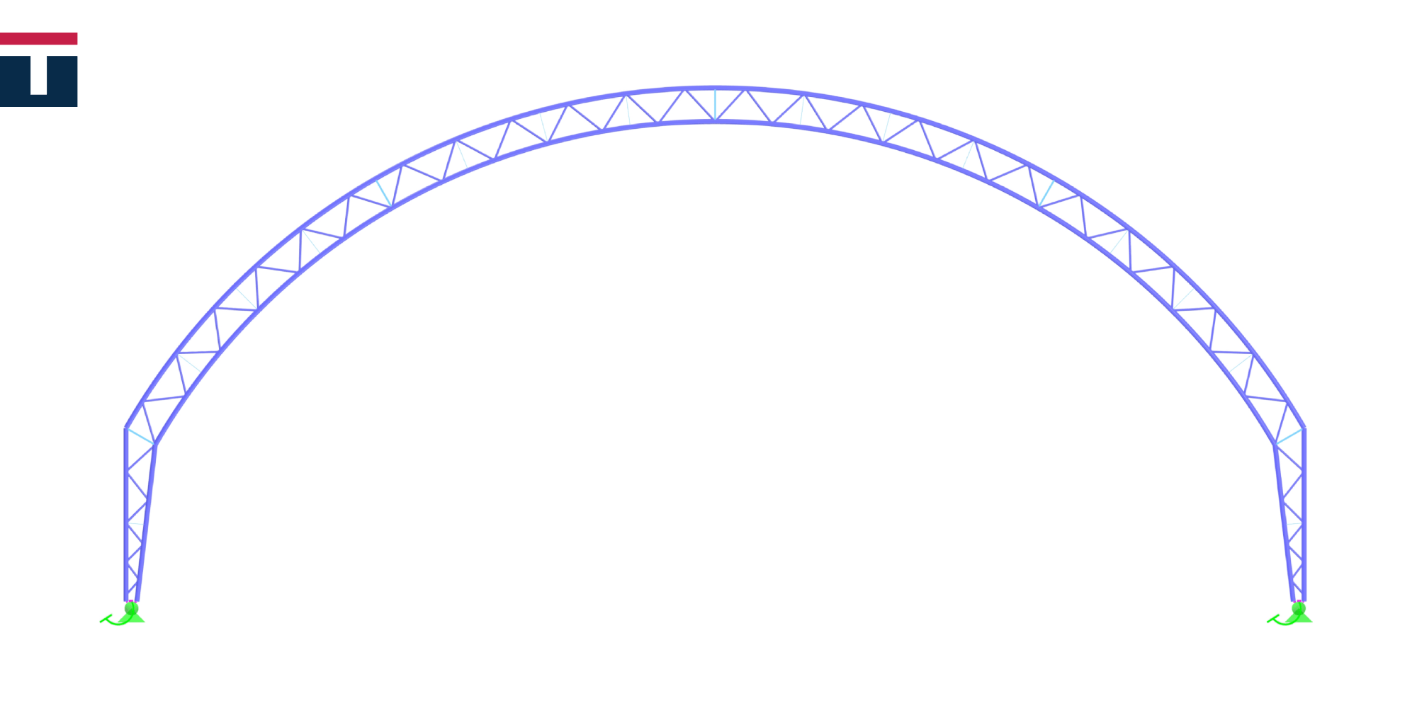
The situation is similar with pressure coefficients for roofs. When appropriate cases cannot be found in an official standard, we must look for another way to determine the values. We have encountered one such case, having designed a hall with arched trussed roof for the US market. This specific case meant that the wind load analysis is performed against ASCE7. However, the standard fails to provide coefficients for arched roof geometry so, upon ensuring approval from a US-licensed engineer, we determined the load values and distribution in accordance with the Canadian standard NBC that contains coefficients for this type of roof.
It is extremely important to note that any application of standards which are not in official use in a particular country (such as using the NBC in the USA) or standards which are no longer valid (such is the above BS standard) must be specifically highlighted in structural calculation reports and their use must be approved by project team members in charge of oversight, engineering control or similar area of expertise. Before all this, of course, the designer must first assess if using a specific standard is justified, in which they are best aided by understanding the behaviour and interactions of the wind and the analysed structure.
Canopies
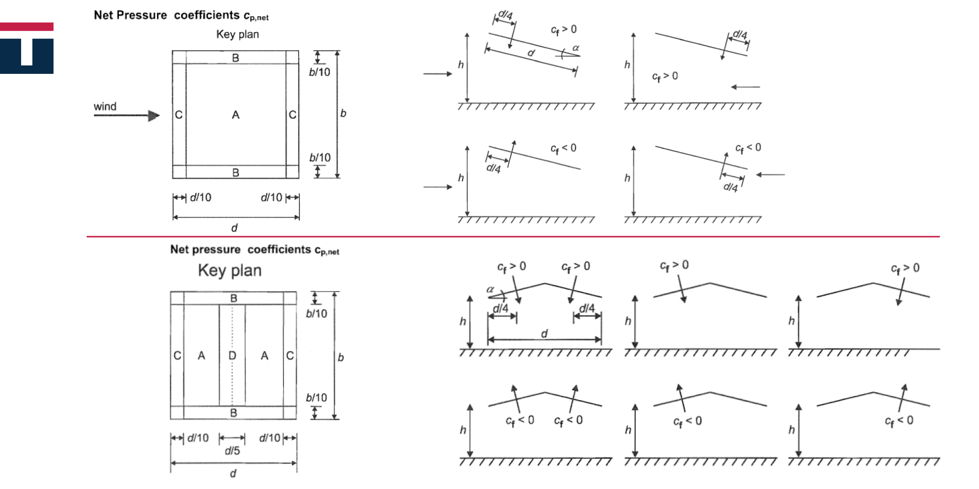
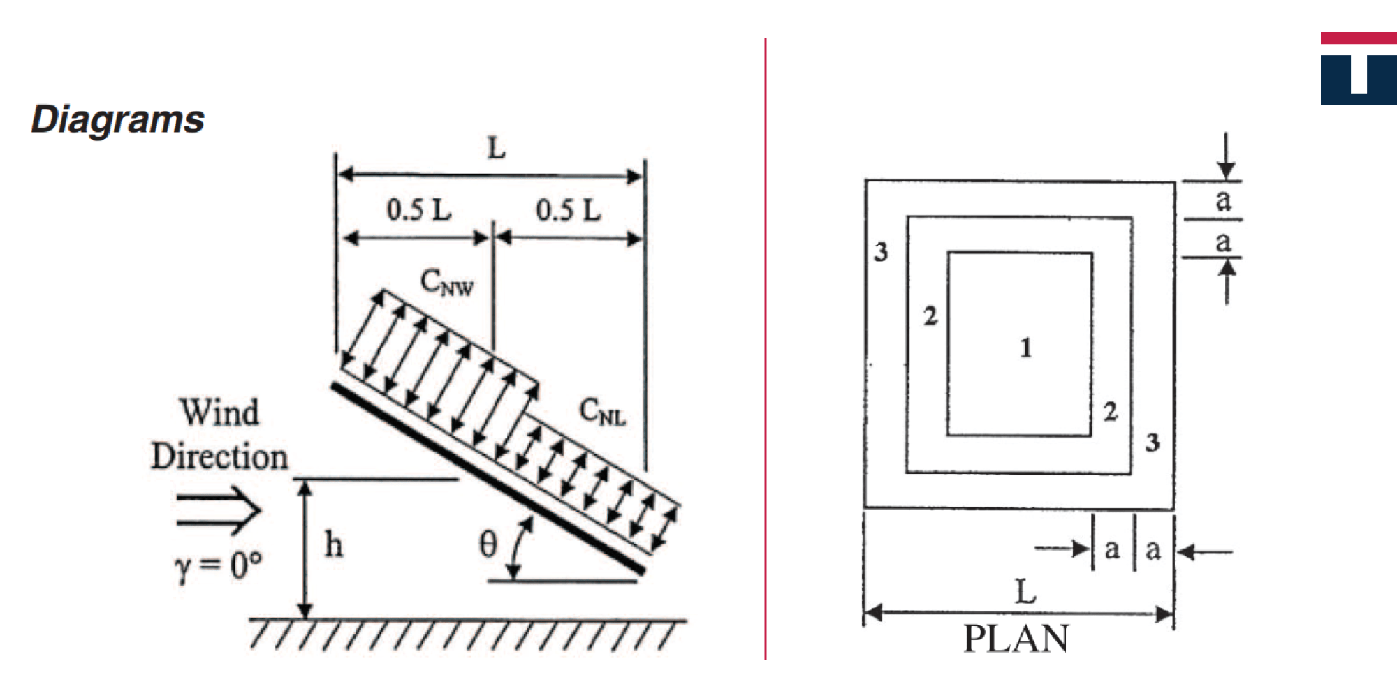
In terms of the wind load analysis, canopy roof is defined as a roof of a structure without permanent walls. This is important because the air flow here is different from that in a walled building. Another aspect which is pertinent for the air flow is the presence of obstacle preventing the air from flowing freely under the canopy. The Eurocode refers to this as the degree of blockage and the force intensity varies depending on this coefficient because different pressure force coefficients are given for different values of the degree of blockage – the higher the degree, the greater the wind pressure action on the lower part of the roof. It is crucial to differentiate between the overall force coefficient (cf) and the net pressure coefficients (cp,net) listed in Eurocode tables.
The overall force coefficient is used to determine the resulting force acting on the roof, while the net pressure coefficients are used to obtain local pressures, which are the highest along the roof edges and used to calculate the roof covering and its elements connecting it to the structure. Looking at the coefficient tables, we can see that the net pressure coefficients are higher than the overall pressure coefficient, which can easily lead to a confusion that this case is the least favourable and should thus be used in structural calculations. However, if we look at the picture in Tables 7.6 and 7.7 in the Eurocode, the zones with the pressures obtained through the net pressure coefficients are symmetrically distributed along the roof contour, while the zones with the highest coefficient values spread across a relatively small area along the roof edges. Conversely, if we look at pictures 7.16 and 7.17 in the Eurocode, we can see that the resulting force obtained through the overall force coefficient acts at a distance from the windward sides equal to one fourth of the roof length parallel to the wind blowing direction.
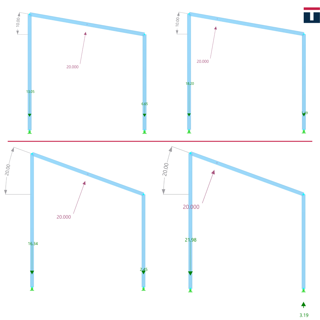
What can we infer from all this? Let’s imagine that we have a canopy with a flat square roof supported by columns at all four corners. If the wind load is symmetrical, there will be a single resulting force acting in the roof’s centre of gravity, i.e. in the roof centre, at the d/2 distance from the columns. This force will be equally distributed onto the columns of the structure as a tensile force in them, which is further transmitted to the base via anchors (of course, we assumed this to be a steel canopy, but the point is the same for any type of material). Knowing the fundamentals of statics, however, we can conclude that if the force is closer to the support (in this case, the column), such as the force obtained via cf, the reaction of the adjacent support is therefore greater – in this case, it is the tensile force in the column and further in the anchors. This can lead to a situation that even if the resultant of the symmetrical load of cp,net is greater than the total force, the relevant support reaction may be greater in case of the force cf. The steel column is not likely to be affected by the increased tensile force (yet the increase in force should definitely be taken into account); the challenge, however, lies with the anchors, the concrete surrounding them and the increased uplift force disrupting the overall stability, i.e. the uplift of the foundation. This could easily be the case if the foundation is calculated on the basis of concrete capacity criteria, where the adopted foundation has small dimensions, i.e. has low weight, which cannot counteract this uplift force. Of course, when we talk about the overall stability, this is not the only effect which can be incorrectly analysed by using the symmetrical load. In the case of a sloped roof, since the resulting force acts on one quarter of the length, we get a larger overturning moment, which again disrupts the overall stability of the structure, while causing a different distribution of forces in the supports. This effect increases as the roof slope angle rises, which is illustrated by an analysis we did and presented in the pictures below.
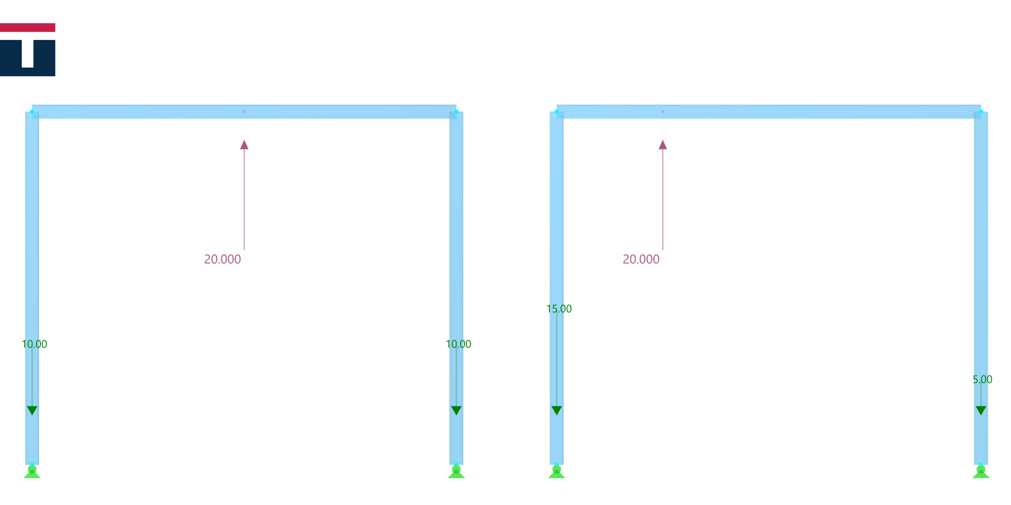
The first picture shows the effects that occur in flat roofs. As stated above, we can intuitively conclude that the support reaction is greater when the force is closer to the support.
The second picture shows the effects on the roof slope. Due to the additional effects of the overturning moment acting on the entire structure, we can see that not only the support reaction nearer to the resultant wind force (left support) is greater than when the force acts on the middle of the span, but also the support reaction further away from force (right support) can have a different sign! The reaction intensity and sign certainly depend on the geometry of the structure and on the value of the wind force, but this goes to show that we can underestimate the value of the force in the column and its connection to the foundation by incorrectly adopting the coefficients.
A similar situation with the pressure force coefficients can be found in ASCE7, although it is less likely to confound (in my opinion) since the force coefficients are clearly separated by chapters. Force coefficients for the main structure (dubbed Main Wind Force Resisting System or MWFRS in the standard) are given in separate chapters (two different procedures), while the pressure coefficients for claddings are given in a different chapter. If we look at the pressure distribution on the roof for the MWFRS, the higher force values are clearly those closer to the windward side, while the situation with the cladding calculation is very similar to that of the Eurocode – local pressures are the highest along the roof edges and decrease towards the middle.
What if there is a wall?
Let’s return to the degree of blockage. In the Eurocode, the blockage is described as an obstacle to the air flow such as vehicles or stored goods (at least judging from the sketches given in the canopy roof chapter). But a blockage can be a wall too. On the other hand, we saw that a canopy is defined as a structure without permanent walls. Despite this definition, we can consider this roof as a canopy roof, because ultimately what matters is the nature of the air flow under the roof, not the definition of the canopy in a standard. This is mentioned for another reason though: how is such a wall to be analysed for wind actions? And what if there is more than one wall? The Eurocode, unfortunately, fails to address this situation. Surely, if there is a wall, we can analyse such a case according to the rules for walls and parapets provided in the corresponding chapter. If, however, there is more than one wall, the situation gets slightly more complicated. We can certainly continue to use the previously mentioned rules and make certain approximations, but will the real air flow and wind pressure be represented in this way and all the necessary directions analysed? Also, these cases can be categorized as open buildings, but we still mention them in the part concerned with canopies. In this case, we can also turn to former standards such as the German standard DIN 1055-4 or the abovementioned BS 6399-2 for help. These standards acknowledge this situation and provide internal pressure coefficients for buildings open on one, two or three sides, as well as relevant wind directions that should be analysed. ASCE 7 also classifies buildings according to the degree of openness of the building envelope and gives internal pressure coefficients accordingly.
CFD Analysis
Advanced analysis using some of CFD (Computational Fluid Dynamics) software tools available on the market can be used for the cases not covered by the standards. We used a trial version of the RWIND software for designing a carport structure enclosed on three sides (or according to some definitions, a building open on one side) in order to achieve a better perception of the air flow around and inside the carport, and to be able to compare these results with the results from the corresponding standards listed above. Although we are no experts in the CFD analysis (at least not yet), the results we achieved seem realistic to us and are comparable to the information from the standard.
This concludes the first part of the article, in which we discussed the most important aspects to consider when analysing the wind load of buildings and canopies. The article will next focus on other types of structures such as bridges, lattice structures, and chimneys.
We hope you find the article useful and providing a clearer insight into the importance of the wind load analysis. We look forward to bringing more details to you in the next one and invite you to follow us to learn more about the safety aspects of designing different types of structures.


