FEA in structural design
Every aspect of engineering requires comprehensive and accurate calculations as proof of a safe and reliable design. These calculations are based on mathematical formulas and equations that could be so complex that we would have to spend hours, or even days, in order to solve them by hand. And what if the output shows that our design has to be changed? We would have to repeat the calculations over and over again until we have found proper solutions. You can imagine how exhausting and time-consuming a job this can be. Luckily, there is a tool that can help engineers with that – the Finite Element Analysis, better known by its abbreviation – FEA.
Many engineers use the FEA – mechanical, nautical, electrical, geotechnical and structural engineers are among them. They use FEA for solving different kinds of problems related to statics, dynamics, stability, heat transfer, electromagnetic potential and much more.
For the purposes of structural design , information like deflections, stresses, strains, forces and frequencies are required in order to check the resistance of a structure.
There are various types of structures – residential and commercial buildings, industrial buildings, bridges, silos, tanks, chimneys, dams and so on. And there are also different types of finite elements. A basic categorization is by their shape: 1D finite elements (or beam elements), 2D finite elements (or plate/shell elements) and 3D finite elements (or solid elements). There are more divisions among them, but they will not be discussed here.
As mentioned, we have different types of structures and different types of finite elements. As you may assume, there is a connection between those two. When we create an analytical model of a structure, it consists of finite elements, while the type of structure dictates which type of the FE will be used. Columns, beams, bracings or any other member can be represented with 1D finite elements, as their length is, in most cases, much bigger than the other two dimensions. You can now recognise the origin of their names – 1D stands for one predominant dimension. Consequently, 2D finite elements are those that have two significantly bigger dimensions than the third one (thickness) and if we want to create a slab or a wall in our model, we would use 2D finite elements here. And finally, we have 3D finite elements where all three dimensions are taken into account. It gets a little tricky when it comes to the usage of these elements. You would use them for modelling something massive, like a dam or maybe a very thick foundation. However, they can be used for modelling slabs and walls as well as 2D elements. On the other hand, this would require more computation time and if there is no strong reason for modelling it with 3D elements, it should be avoided. There are many pros and cons for using 3D finite elements, but we will leave this for another post, as this can be a topic of itself. Nonetheless, the following outcome can be seen – anything that is modelled with 1D elements can be modelled with 2D elements also, and anything modelled with 2D elements can be modelled with 3D elements. It all depends on the situation and on the engineer’s decision.
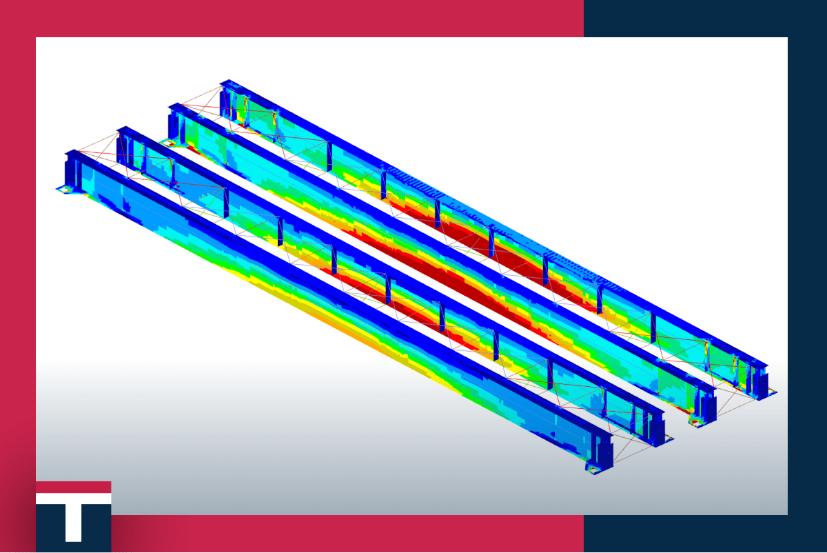
As we are experts in structural steel design , our models mainly consist of 1D and 2D finite elements. One typical example of FEA usage in structural steel design is a model of an industrial building. This three-dimensional model (don’t confuse with 3D finite elements) would be created with 1D elements that will form the whole structure. In the first step, we would obtain all the results that are required for checks like the stability control of the structure or the strength control of the bearing elements, and in the next step we would conduct local checks. In the steel design, most common local checks are related to the connection design . Here we also use the FEA methods to analyse connections, and in this case, local models of 2D finite elements are employed. One more example of local check would be a beam check for lateral torsional buckling. This check can be conducted on a beam created from the 1D element and calculated by equations given in codes (Eurocode, AISC, AS4100 and any other steel design code) and a linear buckling analysis can also be run on a model created from 2D elements. It is at the discretion of the engineer.
With all this in mind, we can draw a conclusion – the FEA is a powerful tool that can be used for simulating almost any process in the nature, from the deflection of a simple supported beam under uniform load, to analysing soil movement during earthquake (which is pretty complex to analyse). However, I think that we need to underline that the FEA is a tool, and it’s the engineering knowledge and experience that are the vital component for solving any kind of problem. Many can be taught to apply a FEA tool, but would they be able to distinguish a good from a bad outcome? For that reason, we are constantly developing our skills, both in engineering and in FEA, so that we can stand behind our designs and be fully confident about them.