NONLINEARITIES IN FEA
In our previous article we have explained how we can use FEA in structural engineering, concluding that the FEA is a great tool for solving numerous problems in structural engineering (actually, in any branch of engineering). Now, we are going to take a deeper look at the types of analysis that we can perform.
The most elementary method for running the FEA is linear analysis. And what does “linear” represent? If the analysis were completely linear, all the equations that FEA software has to solve would be linear and the results that we want to obtain could be simply determined from the relation of loads and the initial stiffness of the model in one go. None of the factors that could disturb that linear relation would be taken into account – the geometry of the structure, material properties, unidirectional supports, their partial activity, and so on. However, in reality, structures do not behave in a linear way. Firstly, loadings are not applied simultaneously on structures. Structural elements are being deformed under the influence of those loads and that deformation affects further force distribution among elements. The relation between the force and the deformation varies among different material types. All that leads to nonlinear FEA calculation.
How does geometry affect the analysis?
The effect of the structure’s geometry on the analysis will be explained first. As it has already been said, the elements of structures will deform if some force acts on them, since they are not absolutely rigid. Furthermore, we all know the basics of the mechanics and that the moment is a product of force and the distance from the reference point to the object. Hence, if that reference point were in the same line with the force, it would not produce any moment, and thus, the undeformed structure wouldn’t be affected by the moments made of axial forces. Having said that structures always deform under the loads, that would imply that we always have moments produced by axial force, or the so-called second-order moments. That is absolutely true, but there are circumstances when we can ignore them. Surely, we can always account for them, but in some cases that would be unnecessary, as they would not have a significant impact on the design. Situations and rules about considering second-order moments in the analysis and design are described in most of the structural codes that we use, such as Eurocode, AISC, Australian Standards and so on.
And how does calculating the second-order moments affect FEA? Linear approach to the calculation means that after we run the analysis for the loaded structure, the software will simply find out internal forces like moments or shear and axial forces. We will also have insight into the final deformation of the structure, but this deformation has no effect in terms of increasing moments, since the software calculates all the internal forces on the undeformed system. Contrarily, if we decide to perform the geometrically nonlinear analysis, the calculation will be iterative. Loads must be applied incrementally, so that with each increment we get a new value of deformation that will affect the calculation in the next step. The software will continue with the iterative calculation until it finds equilibrium for the given system.
Materials with nonlinear properties
Material nonlinearity comes next and it will be described for the case of structural steel material model. Let’s imagine a steel beam that is loaded uniformly by its entire length. When the load is applied, the beam will deflect and when the beam is unloaded, it will go back to the initial shape. However, you may assume that there is some level of deflection when the beam would not be able to retain its original shape. This will happen when the steel reaches its yield strength after which it enters the plastic zone of its material diagram. Ability for developing plastic deformations is one of the most beneficial properties of the steel. When we use linear material model in our calculation, software cannot use plasticity of the steel, because it just not exist in that model. You may know how stress-strain curve for the steel looks like:
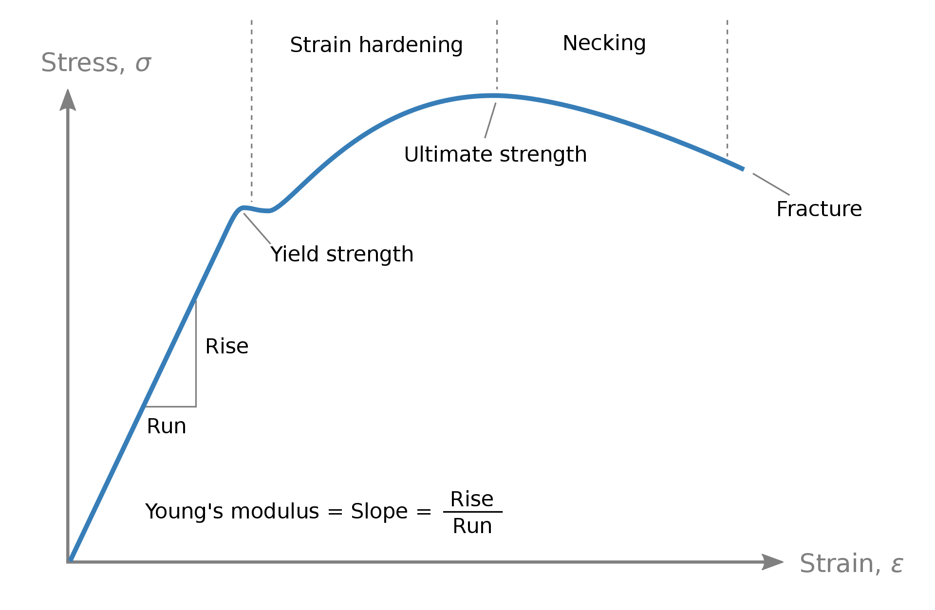
In a case of the linear model, the part of the stress-strain curve after the yield strength point (plastic plateau) doesn’t exist – the diagram continues to be linear in the form of an infinite line. This means that if the loads were continuously increased, the stress would also increase in a linear relation and it can go far beyond the yielding limit (to the infinity). That, of course, is not possible. When the strains (resulting from deformations caused by the loads acting on the element) in our model reach the plastic zone, the stresses will just slightly increase after that, while the cross section goes plastic. If we want to account for these effects of the material in our FEA calculation, a nonlinear material model must be used. The software will calculate strains based on the deformations and then the corresponding stresses. If the strains enter the plastic zone of the diagram, every further load increase will result in the strain development, while the stress will be held on its yielding limit (or it would be higher to some extent). Of course, there are limitations for plastic strain level, and they could be found in structural codes. Structural codes also contain recommendations about applying material nonlinearity in FEA model, since implementation of the real stress-strain curve in the software is rather complicated.
Working as structural steel designers , we have explained how material nonlinearity works for the steel. However, there are many materials with nonlinear (elastic and/or plastic) properties, which behavior can be exceedingly different than the behavior of the steel. These material properties can be found in the appropriate literature, or they can be obtained from the laboratory tests.
Nonlinearities related to supports and element types
Finally, nonlinearities can be related to the boundary conditions and member or surface types. We can set our supports to be ineffective for tension or compression, to include friction into calculation or to include certain slippage of the support. Good example for ineffectiveness of the support is restraining foundation slab in a vertical direction. Soil (let us assume solid rock for purposes of the example) under the foundation prevents its downward movement, and thus, movement of the whole structure. On the other hand, it does not restrain possible upward movement (nor it can transfer tension forces in the contact). In this case, proper way for assigning support to the foundation slab would be creating of surface support that is ineffective for tension (or for the uplift). Or imagine steel beam simply supported onto two walls, without any anchorage. Neither here we don’t have possibility to prevent beam from the uplift, since it is not fixed to the wall. For that reason, we should assign supports with mentioned nonlinearity to the beam ends. But what about horizontal movement? Some might say that the beam is unrestrained in the horizontal direction. However, thanks to the friction, we have some resistance to this displacement. Friction can be assigned as a nonlinearity to the supports, or it can be modeled as an input parameter for contact. Contact itself is the whole new category of nonlinearity. Keep following our website and social media to find out more on that topic in some of our further blog posts.
In many software you have options to assign different types for the members, such as ‘beam’, ‘truss’, ‘rib’, etc. Among them, ‘tension only’ or ‘compression only’ members often can be found. If this property is given to the member, it will absorb only ‘requested’ force. That means that if the other ‘undesirable’ force occurred in the first iteration of the calculation, in the next iteration this member would be neglected. Just don’t confuse ‘tension only’ members with cables. Although they are unable to absorb compression force, and are therefore subjected to tension, cables require prestress in order to maintain structural stability and to carry other loads, and that leads us back to the geometrical nonlinearity. However, to shorten the already long text, this kind of nonlinearity will be explained in another separate article.
With all this in mind, it can be concluded that the described situations present real-life structural behaviour and that using nonlinear FEA brings our models closer to reality. Therefore, we at Tim Global Engineering do not hesitate to use nonlinear FEA calculations whenever it is necessary to obtain safe and accurate results. Still, nonlinear calculations are very demanding, and they can be very time-consuming. It is up to the engineer to decide whether applying a nonlinear calculation is justified or not. One thing is for sure: when it comes to the safety of structure, no compromise should be made when performing exact analyses and design.